Date Completed: September 18, 2003
Fading is one of the important obstacles which limits the wireless transmission. Deep fading will cause loss of signal at the receiver. The transmitted signal will arrive at the receiver antenna through multiple paths which causes what is known as multipath fading. Each path has its own delay and attenuation and the received signal amplitude is the collective effect of the signals arrived through different paths.
The aim of this simulation is investigating the effect of the mentioned channel which is known as Rayleigh Fading Channel. This will be achieved by simulating the channel and investigating the received signal's amplitude probability density function which will be shown that it has a Rayleigh distribution.
The variation of the received signal amplitude caused by multipath fading, which is also known as multiplicative noise in comparison with additive noise that is caused by thermal effects, will be demonstrated.
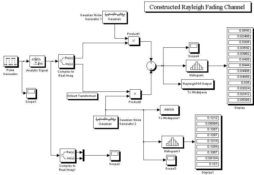
The simulation can be depicted using the schematic diagram below (The Simulink model):
If we choose the transmitted signal to be ![]() , we therefore can model the received signal as
, we therefore can model the received signal as ![]() because of slow signal fading in the communication system. r and θ represent amplitude and phase variations respectively caused by multipath effect of transmission. Signals arrived through multiple paths present either constructive or destructive effect.
because of slow signal fading in the communication system. r and θ represent amplitude and phase variations respectively caused by multipath effect of transmission. Signals arrived through multiple paths present either constructive or destructive effect.
The amplitude and phase variations should be analyzed using statistical math:
If we write ![]() , according to central limit theorem ,x and y will have Gaussian distribution and by considering these relations:
, according to central limit theorem ,x and y will have Gaussian distribution and by considering these relations: ![]()
![]()
![]()
![]()
we can conclude that the amplitude of the received signal through a multipath channel will have a Rayleigh distribution: ![]()
This distribution is depicted in the diagram below :
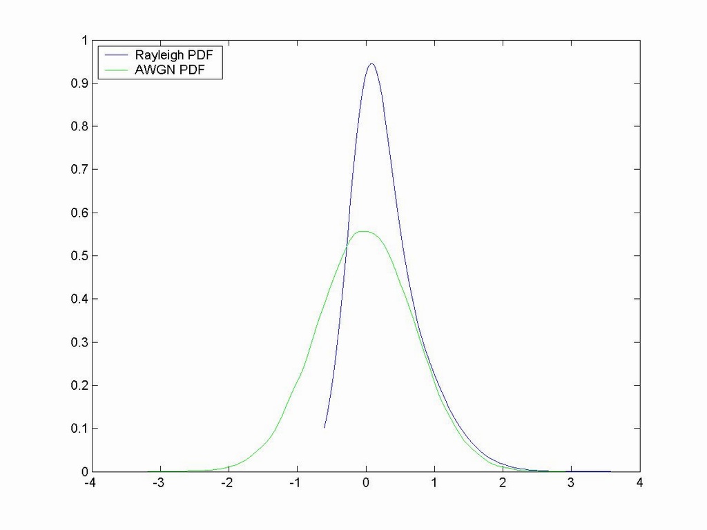
-The negative values of Rayleigh distribution in the above diagram are due to the interpolation function used and should be ignored in the analysis.
Program Execution Directions (included in the package):
After executing the program, a file named fadingchannelconstructed.mat, which is the output of the program, will be created in the same directory of the executable file. This file can be loaded to Matlab and the PDF of the output data can be verified to have Rayleigh distribution with the following piece of code executed in Matlab (this code also resides in PlotCommands.m file included in the Package) :
[f,x,u] = ksdensity(abs(RayleighPDFOutput.signals.values));
[f,x] = ksdensity(abs(RayleighPDFOutput.signals.values),'width',u*2000);
plot(x,f);
hold on
[f,x] = ksdensity(AWGN.signals.values);
plot(x,f,'g');
legend('Rayleigh PDF','AWGN PDF',2);
Real-time Workshop is configured to compile the Simulink model by this compiler:
Lcc C version 2.4
"fadingChannelConstructed.zip": the package which comprises the Simulink models (Both to-be-compiled one and the full-featured one), Real-Time Workshop produced files and the executable file, the produced PDF figure and its jpg format, and PlotCommands.m file.
"FadingChannel.zip": the package which comprises the Simulink model, the produced PDF figure, and PlotCommands0.m file. (in this model the Multipath Rayleigh Fading Channel block from the communications blockset is used)
"fadingChannelConstructedLPF.zip": the package which comprises the Simulink model, the produced PDF figure, and PlotCommands1.m file. (in this model an LPF designed with Matlab Filter Design Toolbox's FDATool is used to limit the bandwidth of the Gaussian Noise Generators )